An illustration explaining the X, Y, and Z axis movement of a CNC router based on the Cartesian coordinate system.

How Does a CNC Router Work? A Simple Explanation

Written by: Robert Liao

|

Published on

|

Time to read 5 min

Author: Robert Liao, Technical Support Engineer

Robert Liao is an IoT Technical Support Engineer at Robustel with hands-on experience in industrial networking and edge connectivity. Certified as a Networking Engineer, he specializes in helping customers deploy, configure, and troubleshoot IIoT solutions in real-world environments. In addition to delivering expert training and support, Robert provides tailored solutions based on customer needs—ensuring reliable, scalable, and efficient system performance across a wide range of industrial applications.

Summary

Ever wondered how a CNC router works its magic, transforming a block of wood or plastic into a complex shape with seemingly effortless precision? This simple explanation breaks down the core components and process. At its heart, a CNC router uses a computer controller to read digital instructions (G-code) and translate them into precise, coordinated movements of its cutting tool along different axes, effectively automating the work of a master craftsman.


Key Takeaways

A CNC router works by translating a digital design file into physical movements using a computer controller, motors, and mechanical axes.

The process relies on G-code, a specific instruction language that tells the machine exactly where and how fast to move.

The CNC controller is the "brain," interpreting the G-code and sending electrical signals to the motors.

Motors (Stepper or Servo) act as the "muscles," precisely turning these signals into physical movement along the X, Y, and Z axes.

Watching a CNC router glide effortlessly across a piece of material, carving out intricate details, can feel like watching magic. But behind the apparent sorcery lies a beautifully logical system of digital instructions and precise mechanical movements. How does it actually translate a file on a computer into a physical object?

Let's be clear: the fundamental principle is surprisingly straightforward. It's about giving a machine the ability to read a map and follow directions with superhuman accuracy. This guide will simply explain how a CNC router works.

An illustration explaining the X, Y, and Z axis movement of a CNC router based on the Cartesian coordinate system.

The Core Idea: From Digital Map to Physical Path

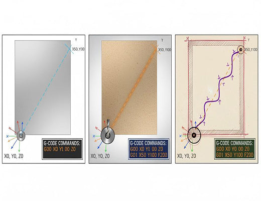
As we discussed in our guide to CNC Router Software, the journey starts with a digital design (CAD) which is then translated into a set of specific instructions called G-code (CAM). This G-code file is the "map" that the CNC router will follow. It contains commands like:

  • G01 X50 Y100: Move the tool in a straight line to position X=50mm, Y=100mm.
  • S18000: Set the spindle speed to 18,000 RPM.
  • M03: Turn the spindle on (clockwise).

The CNC router's job is to read this map and physically execute these movements.

The Anatomy of Motion: How a CNC Router Moves

To understand the movement, you need to know the key players:

  • The Frame & Bed: The rigid structure that holds everything stable.
  • The Axes: These are the tracks or rails that allow movement in specific directions, usually based on the Cartesian coordinate system:
    • X-axis: Left and Right movement.
    • Y-axis: Forward and Backward movement.
    • Z-axis: Up and Down movement (controls the cutting depth).
  • The Gantry or Table: Depending on the design, either a bridge (gantry) moves over a stationary table, or the table itself moves beneath a stationary bridge. This carries the cutting tool along the X and Y axes.
  • The Spindle: Mounted on the Z-axis, this is the high-speed motor that spins the cutting bit.
  • The Motors: These are the crucial "muscles" attached to each axis, responsible for creating the precise movement. They are typically either Stepper Motors or Servo Motors.

The Brain and Nerves: Understanding the Control System

This is where the digital instructions meet the physical hardware.

  • The CNC Controller: This is the dedicated computer—the "brain"—of the CNC router. Its primary job is to read the G-code file line by line.
  • Interpreting the Code: For each G-code command, the controller calculates the exact sequence of electrical pulses needed to achieve the desired movement.
  • Sending the Signals: The controller sends these precise electrical signals through wires (the "nerves") to the motors connected to each axis.
  • Motors Convert Signals to Motion:
    • Stepper Motors: These motors move in discrete, precise "steps" for each electrical pulse they receive. They are cost-effective and common on hobbyist and mid-range machines.
    • Servo Motors: These motors use a feedback loop (an encoder) to continuously report their exact position back to the controller. The controller constantly compares the actual position to the commanded position and makes micro-adjustments. Servos offer higher speed, torque, and accuracy, and are standard on industrial machines.

Putting It All Together: The Cutting Process Explained

So, how does a CNC router work in sequence?

  1. The G-code file is loaded into the CNC controller.
  2. The operator initiates the program.
  3. The controller reads the first line of G-code (e.g., G01 X50 Y100).
  4. The controller calculates the required electrical pulses for the X and Y axis motors.
  5. It sends these signals to the motors.
  6. The motors turn precisely, moving the gantry/table and thus the spindle to the coordinates (50, 100).
  7. The controller reads the next line of G-code, and the process repeats, precisely guiding the spinning cutting tool along the programmed path to carve the material.

Industrial CNC router controllers often feature network connectivity, allowing G-code transfer, remote monitoring, and even edge control integration via gateways like the EG5120.

A block diagram explaining how a CNC router works: the controller reads G-code, sends signals to motors, which drive the axes to move the cutting tool.


Conclusion: Precision Through Translation

At its heart, how a CNC router works is a remarkable feat of translation. It translates abstract digital coordinates and commands from a G-code file into precise, synchronized physical movements of its axes and spindle. It is this accurate and repeatable translation, orchestrated by the CNC controller and executed by the motors, that allows these incredible machines to automate complex cutting tasks with unparalleled precision.


A close-up image showing the key mechanical components responsible for motion in a CNC router, such as linear rails, a lead screw, and a motor.


Frequently Asked Questions (FAQ)

Q1: What is an "axis" on a CNC router?

A1: An axis refers to a direction of movement. A standard 3-axis CNC router moves along the linear X (left/right), Y (forward/back), and Z (up/down) axes. More advanced machines might have rotational axes (A, B, or C) for more complex, multi-sided machining.

Q2: What's the main difference between stepper motors and servo motors?

A2: Stepper motors move in fixed steps based on received pulses (open-loop). They are simpler and cheaper but can lose steps (positional errors) if overloaded. Servo motors use an encoder to constantly report their position back to the controller (closed-loop), allowing for higher speeds, greater accuracy, and the ability to correct for errors. Servos are standard on industrial CNC router machines.

Q3: What is G-code again, in simple terms?

A3: G-code is the basic instruction language for CNC machines. Think of it like a very simple programming language made up of commands starting with 'G' (for preparatory commands, like movement type) and 'M' (for miscellaneous functions, like spindle on/off), followed by coordinates (X, Y, Z) and parameters (like Feed rate 'F' or Spindle speed 'S').