A diagram illustrating the 3-step software workflow for a CNC router: Design in CAD, plan toolpaths in CAM to generate G-code, and execute with Control software.

The Software Behind the Cut: Understanding CAD, CAM, and Control for Your CNC Router

Written by: Robert Liao

|

Published on

|

Time to read 5 min

Author: Robert Liao, Technical Support Engineer

Robert Liao is an IoT Technical Support Engineer at Robustel with hands-on experience in industrial networking and edge connectivity. Certified as a Networking Engineer, he specializes in helping customers deploy, configure, and troubleshoot IIoT solutions in real-world environments. In addition to delivering expert training and support, Robert provides tailored solutions based on customer needs—ensuring reliable, scalable, and efficient system performance across a wide range of industrial applications.

Summary

A CNC router is a powerful machine, but it's only as smart as the software that drives it. This beginner's guide breaks down the essential three-part software workflow behind every cut: CAD (Computer-Aided Design) to create your design, CAM (Computer-Aided Manufacturing) to plan the cutting paths, and the Control Software that reads these instructions and physically moves the CNC router. Understanding this process is key to unlocking your machine's potential.

Key Takeaways

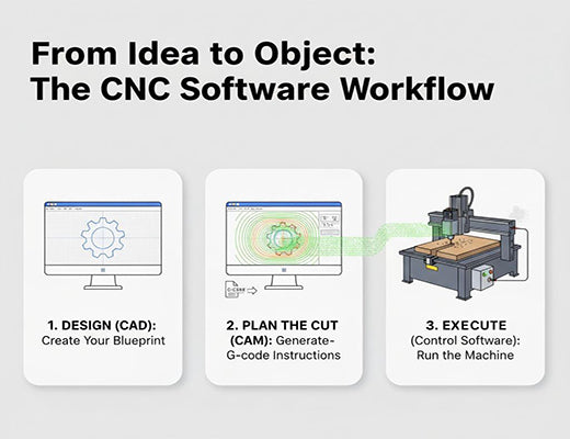
Operating a CNC router involves a three-stage software process: CAD -> CAM -> Control.

CAD software is where you create the digital 2D or 3D design of the part you want to make.

CAM software takes your CAD design and generates the specific toolpaths (cutting instructions) in a language the machine understands, called G-code.

Control Software (often running on the machine itself or a connected PC) interprets the G-code and commands the CNC router's motors to execute the cuts.

You've just unboxed your shiny new CNC router. You've assembled it, plugged it in, and you're staring at the cutting bed, ready to bring your amazing ideas to life. But then you realize: the machine is just sitting there. How do you actually tell it what to cut and how to cut it?

Let's be clear: the physical CNC router is the muscle, but the software is the brain and the nervous system. Understanding the software workflow isn't just helpful; it's absolutely essential to making your machine do anything useful. This guide will walk you through the three key software stages.


A diagram illustrating the 3-step software workflow for a CNC router: Design in CAD, plan toolpaths in CAM to generate G-code, and execute with Control software.


Step 1: Designing Your Vision - The Role of CAD Software

Everything starts with an idea. CAD software is where you turn that idea into a precise digital blueprint.

  • What it is: CAD stands for Computer-Aided Design. It's software used to create 2D drawings (like vector graphics for signs) or 3D models (like furniture parts or molds).
  • Examples: Popular CAD programs range from beginner-friendly options like Easel or Carbide Create, to professional-grade software like Autodesk Fusion 360, SolidWorks, Vectric VCarve/Aspire, or Rhino.
  • The Output: The result of the CAD process is a digital design file (e.g., .dxf, .svg for 2D; .stl, .step for 3D). This file defines the shape of what you want to make. It does not tell the CNC router how to actually cut it.

Step 2: Translating Design to Movement - The Power of CAM Software

This is the crucial translation step. CAM software takes your beautiful design and figures out the practical steps the CNC router needs to take to create it in the real world.

  • What it is: CAM stands for Computer-Aided Manufacturing. It acts as the "virtual machinist."
  • The Input: Your CAD design file.
  • The Process: Within the CAM software, you define:
    • Your Material: Thickness, type (wood, plastic, etc.).
    • Your Cutting Bits: Diameter, shape, number of flutes.
    • Your Strategy: How do you want to cut it? (e.g., Cut on the outside of the line? Engrave along the line? Create a 3D roughing pass followed by a finishing pass?). You also set critical parameters like feed rate (how fast the machine moves) and spindle speed (how fast the tool spins).
  • The Output: This is the 'aha!' moment. CAM software takes all this information and generates a set of highly specific, machine-readable instructions called G-code. G-code is the universal language for CNC machines. It's a text file containing commands like G01 X10 Y25 F300 (Move linearly to coordinates X10, Y25 at a feed rate of 300 mm/min).

Step 3: Executing the Plan - The CNC Control Software

This is the final piece of the puzzle, the software that acts as the CNC router's direct interpreter and commander.

  • What it is: This software (sometimes called a "machine control unit" or "sender") resides either on a computer connected to the CNC router (common for hobby machines) or directly on the machine's dedicated embedded controller (standard for industrial machines).
  • The Input: The G-code file generated by your CAM software.
  • The Process: The control software reads the G-code line by line and translates those commands into precise electrical signals that tell the CNC router's stepper or servo motors exactly how far and how fast to move each axis (X, Y, Z) and when to turn the spindle on or off.
  • Examples: Examples include GRBL (popular for hobby machines), Mach3/Mach4, LinuxCNC, or the proprietary interfaces built by manufacturers like Haas, Fanuc, or Siemens for their industrial machines.

A data flow diagram showing how a CAD design is processed by CAM software into G-code, which is then interpreted by Control software to move the CNC router.


Conclusion: The Digital Thread from Design to Cut

Operating a CNC router is a seamless dance between the digital and physical worlds, orchestrated entirely by software. By understanding the distinct but interconnected roles of CAD (designing the 'what'), CAM (planning the 'how'), and the Control Software (executing the 'do'), you gain the fundamental knowledge needed to transform your creative ideas into precisely machined physical objects. Mastering this digital thread is the key to unlocking the full potential of your CNC router.


An infographic providing a simple explanation of G-code, the command language used by a CNC router, with examples and annotations.


Frequently Asked Questions (FAQ): About CNC router

Q1: Do I need three separate software programs?

A1: Not always. Many modern software packages, especially for hobbyist and mid-range CNC router users, combine CAD and CAM functionality into a single program (e.g., Fusion 360, Vectric VCarve, Easel). However, the Control Software is almost always separate, either running on the machine itself or on a dedicated computer connected to it.

Q2: Is CNC router software expensive?

A2: It varies wildly. There are excellent free and open-source options (like FreeCAD for CAD, LinuxCNC for control), affordable hobbyist-level programs, and professional-grade CAD/CAM suites that can cost thousands of dollars. The right choice depends entirely on your budget and the complexity of the work you plan to do.

Q3: What is the hardest part of the software workflow to learn?

A3: For most beginners, the steepest learning curve is usually in the CAM software. While CAD is about design, CAM requires you to think like a machinist—understanding cutting tools, material properties, and optimal strategies for removing material efficiently and achieving a good finish. This often involves some trial and error.